

Multi-Pole Magnetization: Radial vs. Axial Patterns for Sensor Encoders
Understand the engineering differences between radial and axial multi-pole magnetization in bonded magnets. Learn how to specify the correct pole count and pattern for Hall-effect and MR sensors.
Multi-Pole Magnetization: Radial vs. Axial Patterns for Sensor Encoders
In the world of position tracking, speed sensing, and angular measurement, the mechanical dimension of a magnetic rotor is only half the equation. The other half—often the most critical for signal resolution—is the magnetization pattern.
When designing encoders for BLDC motors, ABS systems, or steering angle sensors using Hall-effect or MR (Magnetoresistive) chips, engineers must specify how the magnetic poles are distributed. Because injection molded magnets consist of magnetic particles suspended in a polymer, they offer unparalleled freedom in configuring these poles during the molding or post-molding process.
This guide breaks down the two most common multi-pole configurations: Radial and Axial magnetization, and when to use them.
1. Radial Multi-Pole Magnetization
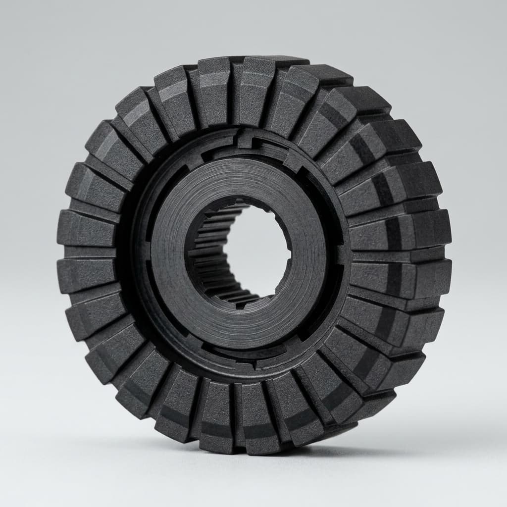
In a radially magnetized ring, the North and South poles alternate around the outer diameter (OD) or inner diameter (ID) of the ring. The magnetic flux lines travel outward from the OD (or inward from the ID).
How It Works
The sensor (usually a Hall IC) is mounted facing the curved outer wall of the magnet. As the rotor spins, the sensor detects the alternating N and S fields passing by.
Key Engineering Characteristics:
- High Resolution: It is possible to pack a very high number of poles (e.g., 24, 48, 64, or even 120 poles) onto the outer circumference, depending on the ring's diameter.
- Signal Sharpness: Injection molded magnets excel here. Because they are isotropic (or can be aligned anisotropically in the mold), we can achieve incredibly sharp transition zones (zero-crossing points) between poles. A sharper transition yields lower jitter in the sensor's output signal.
- Space Constraints: Radial sensing is ideal when the sensor IC can be mounted parallel to the motor shaft, pointing at the side of the rotor.
Common Applications
- ABS (Anti-lock Braking System) Encoder Rings: High pole counts on the outer edge provide high-resolution wheel speed data.
- BLDC Motor Commutation: Providing precise timing for stator coil switching.
2. Axial Multi-Pole Magnetization
In an axially magnetized ring or disc, the poles alternate on the flat circular face of the magnet. The magnetic flux lines travel parallel to the shaft.
How It Works
The sensor IC is mounted facing the flat end (the face) of the magnet, rather than the side.
Key Engineering Characteristics:
- End-of-Shaft Mounting: Axial magnetization is strictly required when the sensor must be mounted at the very end of a spinning shaft (often called "end-of-shaft" or "on-axis" sensing).
- Absolute Position: A common axial setup for steering angle sensors involves a simple 2-pole (diametrical) or complex multi-pole pattern on the face of a disc to provide absolute angular position (0 to 360 degrees).
- Air Gap Sensitivity: Axial setups can sometimes be more forgiving regarding axial play (the shaft moving slightly up and down) depending on the sensor type, but they require strict control over the distance between the sensor and the magnet face (the air gap).
Common Applications
- Electronic Power Steering (EPS) Angle Sensors: Mounted at the end of the steering column.
- Throttle Valve Position Sensors: Where space dictates an end-of-shaft PCB layout.
- Water Meter Impellers: Where the sensor reads through a flat plastic barrier.
Tooling and Manufacturing Considerations
Creating these complex patterns in sintered magnets is notoriously difficult, often requiring several discrete magnet blocks glued together.
For injection molded magnets, the process is highly streamlined but requires specialized tooling:
- In-Mold Orientation: For anisotropic materials (like high-grade NdFeB or Strontium Ferrite), electromagnetic coils are built directly into the injection mold. As the plastic is injected, a massive magnetic pulse aligns the particles into the exact radial or axial multi-pole pattern before the plastic freezes.
- Post-Molding Magnetization: For isotropic materials, the part is molded un-magnetized. It is then placed into a custom-wound magnetizing fixture (a copper coil jig) that discharges a high-voltage capacitor bank to imprint the specific pole pattern.
Specifying Your Magnet
When sending drawings for a multi-pole sensor rotor, always define:
- The exact number of poles (e.g., 48 poles / 24 pole pairs).
- The direction (Radial OD, Radial ID, or Axial face).
- The required peak flux density (Gauss/mT) at a specific air gap (e.g., "Minimum 150 Gauss at 1.5mm air gap").
If you are developing a new rotary encoder and need guidance on achieving the sharpest possible zero-crossing signal, contact the engineering team at Injection Magnets for a DFM and tooling review.
Author

Categories
More Posts
Injection Molded Magnet Tolerances: How to Specify Net-Shape Precision Without Cost Overruns
Injection molded magnet tolerances explained: compare standard vs. precision limits, avoid drawing over-specification, and request a DFM review before RFQ.
Injection Molded Hybrid Magnets (NdFeB + Ferrite): Balancing Cost and Performance
See when injection molded hybrid magnets balance NdFeB flux with ferrite cost, with limits, sourcing checks, and RFQ guidance.

Overcoming Demagnetization: High-Temperature Stability of Bonded NdFeB
Demagnetization at high temperatures is a critical failure mode in EV and automotive motors. Learn how Intrinsic Coercivity (Hcj) and polymer binders dictate the thermal survival of molded NdFeB magnets.