
How Insert Molding Overcomes Magnetic Assembly Failure in Critical Systems
Gluing magnets to steel shafts introduces massive reliability risks under thermal shock. Learn how insert molding magnetic materials directly over shafts creates unbreakable rotor assemblies for automotive and EV applications.
How Insert Molding Overcomes Magnetic Assembly Failure in Critical Systems
In automotive and industrial applications, magnetic rotors are rarely used in isolation. They must be firmly attached to a shaft, a hub, or a carrier to transmit motion or provide position feedback.
Traditionally, manufacturers relied on glue (adhesives) to bond sintered magnets to steel shafts. However, in modern high-performance environments—such as Electronic Expansion Valves (EEVs), coolant pumps, and steering angle sensors—the traditional glued assembly is a primary point of failure.
At Injection Magnets, we solve this problem fundamentally through Insert Molding.
The Physics of Glued Magnetic Assembly Failure
When you glue a brittle sintered magnet to a metal shaft, you create a system with three distinct materials (Magnet, Glue, Metal). The root cause of failure in this system is the drastic difference in the Coefficient of Thermal Expansion (CTE).
| Material | Typical CTE (10⁻⁶/°C) | Behavior under heat |
|---|---|---|
| Stainless Steel (Shaft) | 10 - 17 | Expands moderately |
| Sintered NdFeB (Magnet) | -1 to +7 (highly anisotropic) | Expands very little or unevenly |
| Epoxy Adhesive | 40 - 80 | Expands aggressively |
In an automotive environment experiencing thermal shock (e.g., standard testing cycles from -40°C to +150°C), the steel shaft expands significantly more than the magnet, while the adhesive layer tries to expand massive amounts. The adhesive is forced to absorb the shear stress. Over thousands of cycles, the adhesive fatigues, micro-cracks form, and the bond eventually shears completely.
Once the bond breaks:
- The magnet slips on the shaft, causing immediate loss of sensor calibration (e.g., the steering angle reads 0° when the wheel is turned).
- The motor stalls because torque cannot be transmitted.
- In worst-case high-RPM scenarios, the detached magnet shatters inside the housing.
The Solution: Injection Insert Molding
Insert molding completely eliminates the adhesive variable.
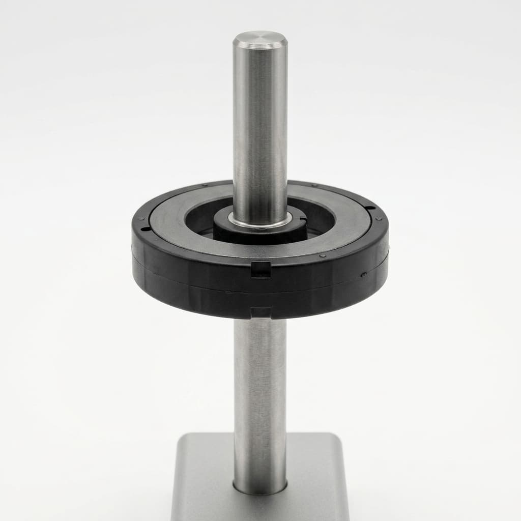
In this process, the bare steel shaft (or brass hub) is loaded directly into the cavity of a plastic injection mold. The heated, liquid mixture of magnetic powder and polymer binder (such as PPS or Nylon) is injected at immense pressure directly around the shaft.
As the plastic cools and solidifies, it naturally shrinks tightly around the metal, forming a unified component.
Why Insert Molded Rotors Survive Thermal Shock
- Mechanical Lock (Knurling): Instead of relying on a chemical glue bond, we design the steel shaft with straight, diamond, or helical knurls. The injected magnetic material flows deep into these grooves. When cooled, it creates an unbreakable mechanical lock that guarantees high pull-out force and rotational torque resistance, even at 150°C.
- Perfect Concentricity (Low Run-out): Gluing a magnet often introduces run-out or eccentricity because the adhesive thickness varies. When a magnet is molded directly onto a shaft, the steel mold cavity perfectly controls the outer diameter (OD) relative to the shaft center. We routinely achieve concentricity of ≤ 0.05 mm.
- Part Reduction & Supply Chain Simplification: You no longer have to manage inventory for shafts, bare magnets, and adhesives. You receive one fully-assembled, validated rotor, ready for final assembly.
- Extreme Environment Ready: PPS (Polyphenylene Sulfide) bonded magnets can withstand constant exposure to hot engine oil, ATF (Automatic Transmission Fluid), and Glycol coolant without degrading, unlike many industrial adhesives which swell or dissolve over time.
Validation: How We Test Insert Molded Rotors
To guarantee reliability for OEM programs, our insert-molded rotors undergo severe validation protocols:
- Thermal Shock Testing: Typically 500 to 1000 cycles from -40°C to +150°C, with rapid transfer times (< 30 seconds). We measure torque retention before and after.
- Torque-to-Failure Testing: The shaft is clamped, and the magnet is twisted until failure. Insert-molded parts with proper shaft knurling routinely exceed the maximum torque output of the motor by a factor of 10x.
- Pull-out Force: Measuring the axial force required to strip the magnet off the shaft.
Designing Your Next Rotor
If you are experiencing adhesive failures in the field, or if you are designing a new EEV stepper motor or sensor rotor that must survive severe automotive testing, it is time to upgrade your assembly method.
Our factory specializes in one-shot insert molding of NdFeB and Ferrite compounds over custom shafts. We offer extensive support in DFM (Design for Manufacturing) to optimize your shaft knurling and mold flow.
Reach out to the Injection Magnets Engineering Team to review your rotor drawings today and eliminate glue from your assembly line.
Author
Categories
More Posts
Injection Molded Magnet Tolerances: How to Specify Net-Shape Precision Without Cost Overruns
Injection molded magnet tolerances explained: compare standard vs. precision limits, avoid drawing over-specification, and request a DFM review before RFQ.

Injection Molded Hybrid Magnets (NdFeB + Ferrite): Balancing Cost and Performance
See when injection molded hybrid magnets balance NdFeB flux with ferrite cost, with limits, sourcing checks, and RFQ guidance.

Multi-Pole Magnetization: Radial vs. Axial Patterns for Sensor Encoders
Understand the engineering differences between radial and axial multi-pole magnetization in bonded magnets. Learn how to specify the correct pole count and pattern for Hall-effect and MR sensors.