
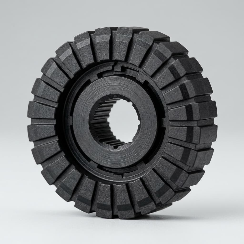
Injection Molded Magnet Tolerances: How to Specify Net-Shape Precision Without Cost Overruns
Injection molded magnet tolerances explained: compare standard vs. precision limits, avoid drawing over-specification, and request a DFM review before RFQ.
For modern automotive, industrial, and consumer electronics applications, injection molded magnets represent a massive leap forward in manufacturing efficiency. By blending magnetic powders (like NdFeB or Strontium Ferrite) with thermoplastic binders (like PA6, PA12, or PPS), engineers can produce complex magnetic components in a single step.
One of the most heavily marketed advantages of this process is net-shape precision. Unlike sintered neodymium magnets that emerge from the furnace as rough blocks requiring expensive, time-consuming secondary grinding and slicing, injection molded parts come out of the mold ready to use.
However, this marketing promise often creates a trap for procurement teams and mechanical engineers. Accustomed to the extreme precision of CNC machining or the post-grinding of sintered magnets, engineering teams frequently default to extreme tolerances on their drawings—often demanding $\pm$ 0.01 mm or $\pm$ 0.02 mm across all dimensions.
In the world of injection molding, over-specifying tolerances is the fastest way to double your tooling costs, increase your piece price due to high scrap rates, and delay your project by months during the mold tuning phase.
This guide is designed for buyers, procurement teams, and engineers to understand the true boundaries of injection molded magnet tolerances, how material shrinkage impacts precision, and how to specify requirements that keep costs under control while guaranteeing performance.
Applicability note (Global, last reviewed 2026-07-19): The tolerance ranges below are planning baselines for net-shape injection molded magnet RFQs, not universal drawing guarantees. Validate final limits against part size, wall thickness, gate location, magnetic alignment, binder datasheet, expected CPK, and the supplier's mold trial data before releasing production drawings.
The Reality of Net-Shape Manufacturing: Shrinkage and Flow
To understand why asking for a $\pm$ 0.01 mm tolerance on an injection molded magnet is a recipe for budget overruns, we must first look at the physics of the injection molding process.
When a magnetic compound is heated and injected into a steel mold cavity, the polymer binder expands. As the mold cools and the part solidifies, the polymer matrix shrinks. This shrinkage is not perfectly uniform. It depends on:
- Flow Direction: Polymers shrink differently in the direction of the melt flow compared to the transverse direction.
- Magnetic Alignment: If the part is being aligned by an external magnetic field inside the mold cavity (anisotropic molding), the physical orientation of the magnetic particles can alter the shrinkage behavior.
- Wall Thickness: Thicker sections of a magnet cool slower and shrink more than thin-walled sections, which can lead to warping or non-uniform outer diameters.
- Powder Loading: A compound with 65% volume magnetic powder will shrink differently than one with 55% volume, because the metal powder does not shrink—only the polymer does.
The mold designer must predict this shrinkage and cut the steel slightly larger than the final part. While modern mold-flow simulation software is highly accurate, it is rarely perfect on the first try. Hitting standard tolerances usually takes one or two tuning loops (modifying the steel). Hitting ultra-precision tolerances can take four or five tuning loops, drastically increasing the lead time and engineering cost.
As the chart illustrates, moving from a standard $\pm$ 0.05 mm tolerance to a precision $\pm$ 0.03 mm tolerance increases costs moderately, mostly in tooling. However, pushing for $\pm$ 0.01 mm causes costs to skyrocket exponentially, often requiring secondary grinding or exceptionally low-cavitation molds with constant process monitoring.
Standard vs. Precision Tolerances: The Engineering Baseline
When negotiating a drawing with your engineering team or your magnet supplier, it is crucial to separate the dimensions into "Standard" and "Precision" categories.
Standard tolerances can be achieved consistently across multi-cavity molds (e.g., 4, 8, or 16 cavities) running continuously for thousands of shots. Precision tolerances require tighter process controls, slower cycle times, and often fewer cavities (e.g., 1 or 2 cavities), which increases the piece price significantly.
The table below outlines the general capabilities of the injection molding process for magnetic compounds based on dimension types.
| Dimension Type | Typical Size Range | Standard Tolerance (Lower Cost) | Precision Tolerance (Premium Cost) | Primary Cost Driver for Precision | Process Limitations & Notes |
|---|---|---|---|---|---|
| Outer Diameter (OD) | 10 mm - 50 mm | $\pm$ 0.05 mm | $\pm$ 0.03 mm | Mold cavity tuning & wear | Achievable in multi-cavity molds if shrinkage is perfectly calculated. |
| Inner Diameter (ID) | 5 mm - 30 mm | $\pm$ 0.05 mm | $\pm$ 0.02 mm | Core pin replacement | Core pins wear over time from abrasive magnetic powder; strict ID requires frequent tool maintenance. |
| Overall Length (Thickness) | 2 mm - 20 mm | $\pm$ 0.08 mm | $\pm$ 0.05 mm | Gate type and mold parting line | Parting line flash and gate vestige make tight length tolerances difficult without secondary facing. |
| Concentricity (TIR) | Relative to OD/ID | Max 0.08 mm | Max 0.04 mm | Injection gating strategy | Requires highly balanced runner systems to ensure even pressure and prevent core pin shift during injection. |
| Perpendicularity | Face to Bore | Max 0.10 mm | Max 0.05 mm | Cooling rate uniformity | Uneven cooling causes the part to warp slightly, affecting perpendicularity. |
| Insert Over-Molding OD | Varies by insert | $\pm$ 0.08 mm | $\pm$ 0.05 mm | Insert dimensional variation | The tolerance of the metal insert itself contributes to the final tolerance of the over-molded assembly. |
Why Concentricity is the Costliest Callout
If you look closely at automotive sensor rotors (like those used in BLDC motor encoders or steering angle sensors), concentricity is often the most critical dimension. If the magnetic pole shifts off-center relative to the shaft, the Hall-effect sensor will read an erratic signal.
Engineers frequently demand extremely tight concentricity (e.g., 0.02 mm). However, achieving this in an injection molded magnet is incredibly difficult. During injection, the highly viscous, abrasive magnetic compound rushes into the cavity at high pressure. This pressure can physically bend the steel core pin forming the inner diameter. If the pin bends even a fraction of a millimeter, the part loses concentricity.
To achieve high concentricity, molders must use expensive, balanced gating systems (like multi-point hot runners or diaphragm gates) and highly rigid core pins. For procurement, pushing back on concentricity requirements—or exploring insert-molding where the magnet is molded directly onto the final steel shaft—can yield massive cost savings.
The Impact of Material Selection on Tolerances
Not all injection molded magnets shrink the same way. The choice of polymer binder plays a massive role in what tolerances are realistic for a given part. If an engineer specifies a tight tolerance but chooses a highly shrink-prone binder, the supplier will be forced to quote a high scrap rate, driving up the piece price.
PA6 (Nylon 6) - The Moving Target
Nylon 6 is the most common and economical binder. However, it is highly hygroscopic, meaning it absorbs moisture from the atmosphere. A PA6 magnet molded perfectly to a $\pm$ 0.03 mm tolerance on Monday might swell by 0.05 mm by Friday if left in a humid warehouse. Procurement Tip: Never specify ultra-tight tolerances on PA6 magnets unless you also specify strict moisture-barrier packaging and plan to assemble the parts immediately upon opening.
PA12 (Nylon 12) - The Stable Middle Ground
PA12 absorbs significantly less water than PA6 and has a more predictable shrinkage rate during molding. For parts requiring precision outer diameters that must remain stable in humid environments (like automotive exterior sensors), PA12 is the preferred choice, despite the higher raw material cost.
PPS (Polyphenylene Sulfide) - The High-Precision Champion
PPS is a semi-crystalline polymer with near-zero water absorption and exceptional thermal stability. It allows for the tightest possible molding tolerances and maintains them through extreme temperature swings (up to 150°C). If the engineering drawing demands $\pm$ 0.02 mm OD and ID tolerances, the material specification almost certainly needs to be PPS. While PPS resin is expensive and requires hot oil mold heating, it drastically reduces scrap rates for high-precision components.
Sourcing Strategies for Molded Magnets
For procurement teams evaluating suppliers for a new magnetic assembly, the tolerance block on the 2D drawing should be the first topic of discussion. Suppliers who simply accept a $\pm$ 0.01 mm tolerance without pushing back or asking questions are often inexperienced and will likely fail to deliver, or they plan to silently ignore the drawing.
Experienced magnet manufacturers will immediately review the tolerances and request concessions on non-critical dimensions. This is a sign of a mature supplier who understands process capability (CPK) and wants to build a robust, long-term manufacturing process.
Assembly Consolidation: Insert Molding
One of the best ways to bypass tolerance stack-up issues is to utilize insert molding. Instead of buying a magnet with a precise inner diameter, and a steel shaft with a precise outer diameter, and then gluing them together, the magnet is injection-molded directly over the knurled steel shaft.
This eliminates the ID tolerance entirely, eliminates the gluing process, and guarantees perfect concentricity directly from the mold. While the initial tooling for insert molding is more expensive, the total cost of ownership (TCO) for the assembly drops dramatically.
If your RFQ includes OD/ID tolerance below $\pm$ 0.03 mm, concentricity below 0.05 mm TIR, or a PA6 part used in humidity, treat it as a DFM review item before asking suppliers to quote production pricing.
Checklist: Procurement & Engineering Alignment for Molded Magnets
Before sending an RFQ for an injection molded magnet, review this checklist with your mechanical engineering team to ensure the drawing isn't artificially inflating the quote:
- Are all dimensions marked $\pm$ 0.05 mm or looser? If tighter tolerances exist, verify with engineering if they are truly critical for function.
- Is the overall length (thickness) tolerance loose enough to accommodate the gate vestige? (Typically $\pm$ 0.08 mm is recommended).
- Has the operating environment (humidity/temperature) been defined? This determines if PA6 is viable or if PA12/PPS is required for dimensional stability.
- Is the concentricity requirement realistic for molding? (Aim for 0.08 mm TIR; anything tighter may require insert molding or secondary grinding).
- Can the assembly be consolidated? Check if insert-molding the magnet directly onto the mating component reduces overall tolerance stack-up.
- Are critical dimensions clearly separated from reference dimensions? Suppliers base their quality control plan and CPK calculations only on critical-to-function (CTF) dimensions.
Frequently Asked Questions (FAQ)
Can injection molded magnets be post-machined to achieve better tolerances?
Yes, but it defeats the primary cost advantage of the process. Injection molded magnets can be ground or turned, but because they contain abrasive magnetic powders, they rapidly wear down cutting tools. The heat generated during machining can also melt the polymer binder. It is almost always more cost-effective to adjust the design to accept molding tolerances than to add a secondary machining step.
Why does my supplier want to increase the tolerance on the parting line dimension?
The parting line is where the two halves of the steel mold meet. During injection, the high pressure can push the mold halves apart by a fraction of a millimeter (called "flash" or mold breathing). This makes dimensions that cross the parting line inherently less accurate than dimensions contained entirely within one half of the mold.
What is CPK, and why does my supplier say a $\pm$ 0.03 mm tolerance fails their CPK requirements?
CPK (Process Capability Index) measures how well a manufacturing process stays within the specified limits. Automotive standards generally require a CPK of 1.33 or 1.67. A supplier might be able to physically mold a part within $\pm$ 0.03 mm, but the natural variation of the machine, material batch, and cooling time might mean they cannot guarantee 99.99% of parts fall in that range. Widening the tolerance to $\pm$ 0.05 mm allows them to meet the statistical CPK requirement without sorting or scraping parts.
Does the magnetic alignment field affect the physical tolerance?
Yes. Anisotropic injection molded magnets are exposed to a strong magnetic field during injection to align the particles. This field can cause the magnetic powder to group slightly differently, altering the flow of the polymer and affecting the final shrinkage. The mold must be tuned specifically for the magnetic state.
Summary
Injection molded magnets offer incredible design freedom, net-shape manufacturing, and the ability to consolidate assemblies. However, treating them like machined metal components when specifying tolerances will immediately destroy their cost advantages. By understanding the boundaries of polymer shrinkage, separating critical dimensions from standard ones, and collaborating with your supplier on DFM, you can secure high-performance magnetic assemblies at a fraction of the cost.
At Injection Magnets, we specialize in the delicate balance between magnetic performance, polymer science, and tooling precision. If you are struggling with a difficult drawing or want to optimize an existing assembly for cost reduction, contact our engineering team today for a comprehensive design review.
Sources & References
- Injection Molded Magnets and Custom Molded Magnet Capabilities. Magnetstek Technical Resources. Magnetstek.com
- Custom Magnet Manufacturing and Bonded Magnet Application Context. Magnetstek Engineering. Magnetstek.com
- Polyamide (Nylon) Selection Guide and Moisture Behavior. SpecialChem Omnexus. SpecialChem.com
Author

Categories
More Posts
Injection Molded Magnets vs. Sintered Magnets: A Complete Guide for Automotive Sensors
Discover the critical differences between injection molded magnets and sintered magnets. Learn why automotive sensor engineers increasingly prefer molded magnetic rotors for precision, cost-efficiency, and complex geometries.

Overcoming Demagnetization: High-Temperature Stability of Bonded NdFeB
Demagnetization at high temperatures is a critical failure mode in EV and automotive motors. Learn how Intrinsic Coercivity (Hcj) and polymer binders dictate the thermal survival of molded NdFeB magnets.

Injection Molded vs. Compression Bonded Magnets: A Procurement and Engineering Guide
Injection molded vs. compression bonded magnets: compare BHmax, tooling, binders, geometry limits, coating risk, and request a DFM review for OEM programs.